Assembled the first three battery packs. There will be 20 in total. Each pack is 30 parallel (all positives connected to all other positives, and all negatives connected to all other negatives) 3.7 volt 2.3ish Ah cells, which makes each pack 3.7volts and about 69 Ah. When I bolt 20 of these packs together in series (positive buss bars to negative buss bars) the voltage will be 74. I may add one more pack to get it up to about 78 volts…we’ll see.
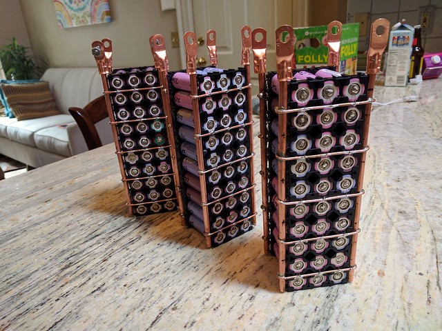
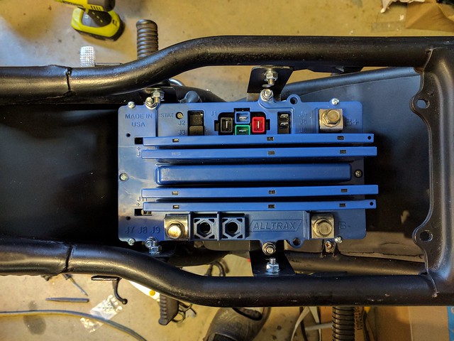
The buss bars are made out of 1/4″ copper refrigeration tubing into which I inserted 8 gauge solid copper. I’m guessing the ampacity of this combo to be between 150 and 170 amps each which would be at least 300 amps total carrying capacity. The controller is capable of delivering 200 amps continuous, but that’s basically at “wide open throttle” Most of my driving will be probably less than half of that.
The ladder rungs are 12 ga solid copper, and the teeny tiny fuse wires that go to each cell is 28 ga tinned copper. These tiny wires should be good up to around ten amps before they melt, which is their intended purpose. If one cell takes a shit, it will hopefully melt the fuse wire, and save the rest of my pack. Without fuse wires like this, one bad cell could conceivably destroy the entire pack.
Here’s a closeup showing the fuses:
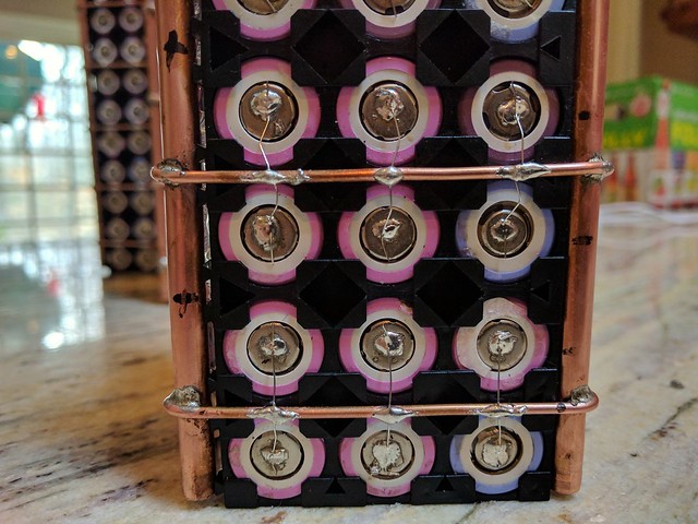
The negative side looks the same.
The “ladder rungs” bend around the tubing, and I make these really tight on the battery holders. Then I run a bead of hot glue on the underside. They seem pretty solid this way.
It’s a lot of soldering, but whatever. It’s no big deal if you’ve got a modicum of will, and a speck of patience. I’ve seen guys crying the blues about how much work it is to make these packs. Only a total pussy would call this work. I yell at the radio while I’m making them, and the times flies right by.